Physical-product prototype testing starts before the prototype is built. First define the requirement, the decision and the evidence. Then choose the article configuration, method and acceptance rule. Without that chain, teams often collect attractive photos, isolated measurements or a successful demonstration that cannot answer the original engineering question.
A practical evidence chain is:
Requirement → Decision → Prototype configuration → Method → Result → Acceptance → Next action
NASA’s systems-engineering guidance distinguishes verification methods such as test, inspection, analysis and demonstration. The useful lesson for a commercial prototype is simple: not every requirement needs the same kind of proof.
The Acceptance Evidence Matrix
| Evidence class | Best used for | Minimum record | Common overclaim |
|---|---|---|---|
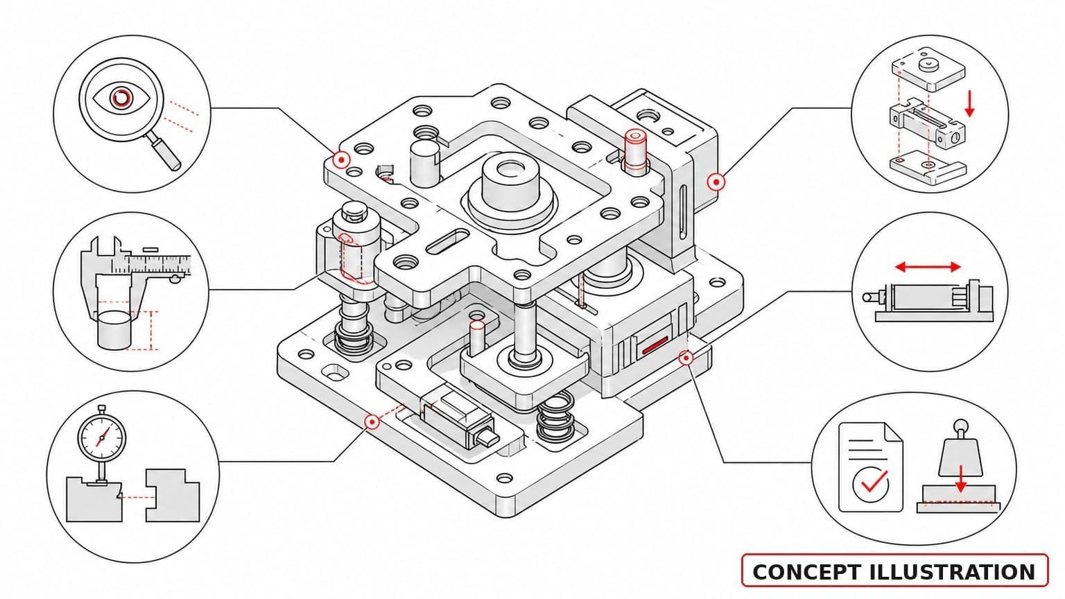
| Visual | Form, presence, finish zones, obvious assembly state | Dated views, controlled angle/light, CAD revision, caption | “Looks right” becomes dimensional or material proof |
| Dimensional | Size, location, form or interface requirements | Characteristic, datum, method, equipment, result, tolerance | One measured feature becomes full inspection approval |
| Fit | Mating, clearance, gap/flush, connector engagement | Mating configuration, interface list, observations and measurements | One successful fit becomes function or life proof |
| Assembly | Sequence, access, orientation, routing | Build sequence, parts revision, issue log, rework notes | Prototype hand assembly becomes production process validation |
| Functional | Defined input/output behaviour | Requirement, setup, conditions, result, acceptance | A demonstration becomes reliability or compliance proof |
| Compliance | Requirement from a law, regulation or standard | Applicable clause, authorised method/lab where required, controlled specimen, report | Internal screening becomes certification |
Step 1: Write the requirement so it can be evaluated
Avoid “the part should fit” or “the prototype should work.” Write the condition and acceptance boundary.
Weak:
The cover should fit the housing.
Stronger:
Cover revision C shall seat against housing revision B without interference at the six identified interface zones; gap observations and the three marked dimensions shall be recorded.
The stronger statement still does not prescribe every method, but it tells the team what evidence is needed.
Step 2: Freeze the test article configuration
Record:
- CAD and drawing revisions;
- material and process only when known and relevant;
- substitute parts or materials;
- firmware/electronics revision, if applicable;
- purchased components;
- assembly state;
- fixture and test setup;
- deviations from intended production configuration.
A test result belongs to a configuration. If the configuration changes, decide whether the evidence still applies.
Step 3: Choose the evidence method
Inspection
Use inspection for visible presence, workmanship conditions, labels, surface zones and other attributes that can be directly observed. Photography can support inspection when angle, lighting, scale and revision are controlled.
Measurement
Use measurement for dimensions, geometry and other quantitative characteristics. A drawing or PMI should identify which characteristics are critical; do not request blanket tight tolerances without a functional reason.
Demonstration
Use demonstration to show an operation or sequence under defined conditions. A video can document movement or assembly, but it still needs the configuration and acceptance rule.
Test
Use a test when a controlled input, environment, duration or load must produce a measurable output. Define equipment, method, units and disposition before testing.
Analysis
Use analysis where a credible model or calculation answers the requirement and physical testing is unnecessary or premature. Record assumptions and input revisions.
Step 4: Separate screening, engineering verification and compliance
Internal screening asks, “Is this direction promising enough to continue?” Engineering verification asks, “Does this configuration meet the defined requirement?” Compliance asks, “Does the controlled product satisfy the applicable external requirement using the required method and evidence?”
Do not label a supplier photo, basic fit trial or internal check as certification. If a regulated or safety-related decision is involved, identify the applicable standard and qualified route separately.
Step 5: Define failure handling before the test
For every failed or ambiguous result, record:
- requirement and article revision;
- observed result;
- whether the setup was valid;
- suspected cause, clearly marked as hypothesis;
- containment or design action;
- whether retest is required;
- which evidence is superseded.
This turns a prototype from a showpiece into a learning instrument.
Evidence Plan template
Requirement / decision:
Prototype configuration and revisions:
Evidence class: Visual / Dimensional / Fit / Assembly / Functional / Compliance
Method:
Conditions and inputs:
Characteristic or output:
Acceptance rule:
Evidence format:
Owner:
Result:
Disposition: Accept / Reject / Investigate / Retest
How the three Project Records should be read
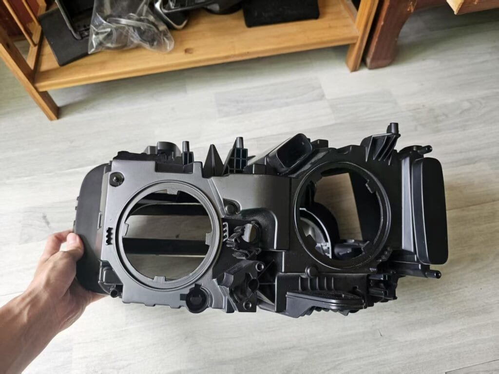
- Headlamp Assembly Prototype: photos/video can document visible form, housing, cover, interfaces and assembly state. They do not prove optical, sealing, thermal or environmental performance.
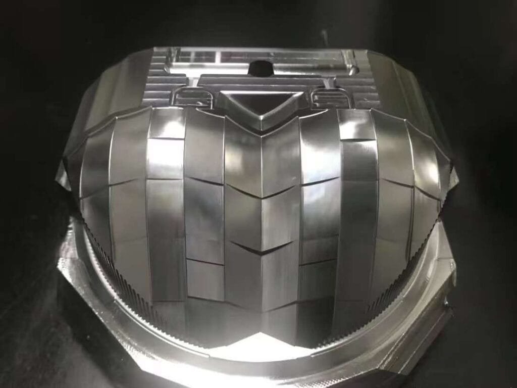
- Lighting Mold Components: photos can document freeform geometry, reflective areas and repeated fine features. They do not prove material, process, tolerance, roughness or optical performance.
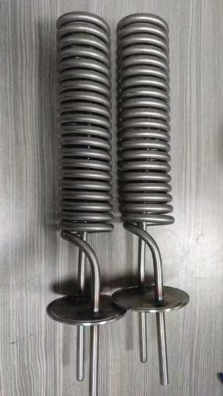
- Helical Cooling Tube: images can connect a drawing view, coil shape, end interfaces, physical assemblies and packaging. They do not prove material, joining procedure, pressure, leak, flow or shipment outcome.
This boundary is not a weakness. Clear evidence limits make a project record more trustworthy.
Pre-quote testing checklist
- [ ] Each requested test links to a decision or requirement.
- [ ] Article revision and substitutions are identified.
- [ ] Method, conditions and acceptance are written before build.
- [ ] Photos, measurements, demonstrations and tests are not treated as interchangeable.
- [ ] Compliance screening is separated from formal certification.
- [ ] Failure and retest handling are defined.
- [ ] Evidence ownership and delivery format are included in the RFQ.
Get Quote
Send your CAD and Evidence Plan with the RFQ. This helps separate what the prototype must show from what it must measure or test.
CTA: Get Quote
FAQ
What is prototype testing?
For a physical product, it is the planned evaluation of a defined prototype configuration against a requirement or decision using inspection, measurement, demonstration, test or analysis.
Is a photo a test result?
A photo can be valid visual evidence when controlled and traceable. It does not prove hidden dimensions, material identity or performance by itself.
What is the difference between verification and validation?
Verification asks whether specified requirements were met. Validation asks whether the resulting product supports the intended use and user need. The exact regulatory meaning depends on the product domain.
Does a functional demonstration prove reliability?
No. Reliability needs defined duration, sample configuration, conditions, method and acceptance evidence.
Sources
- NASA, Systems Engineering Handbook — verification planning and evidence methods: https://www.nasa.gov/wp-content/uploads/2018/09/nasa_systems_engineering_handbook_0.pdf
- NASA, Systems Engineering Handbook Appendix — test, analysis, demonstration and inspection: https://www.nasa.gov/reference/system-engineering-handbook-appendix/
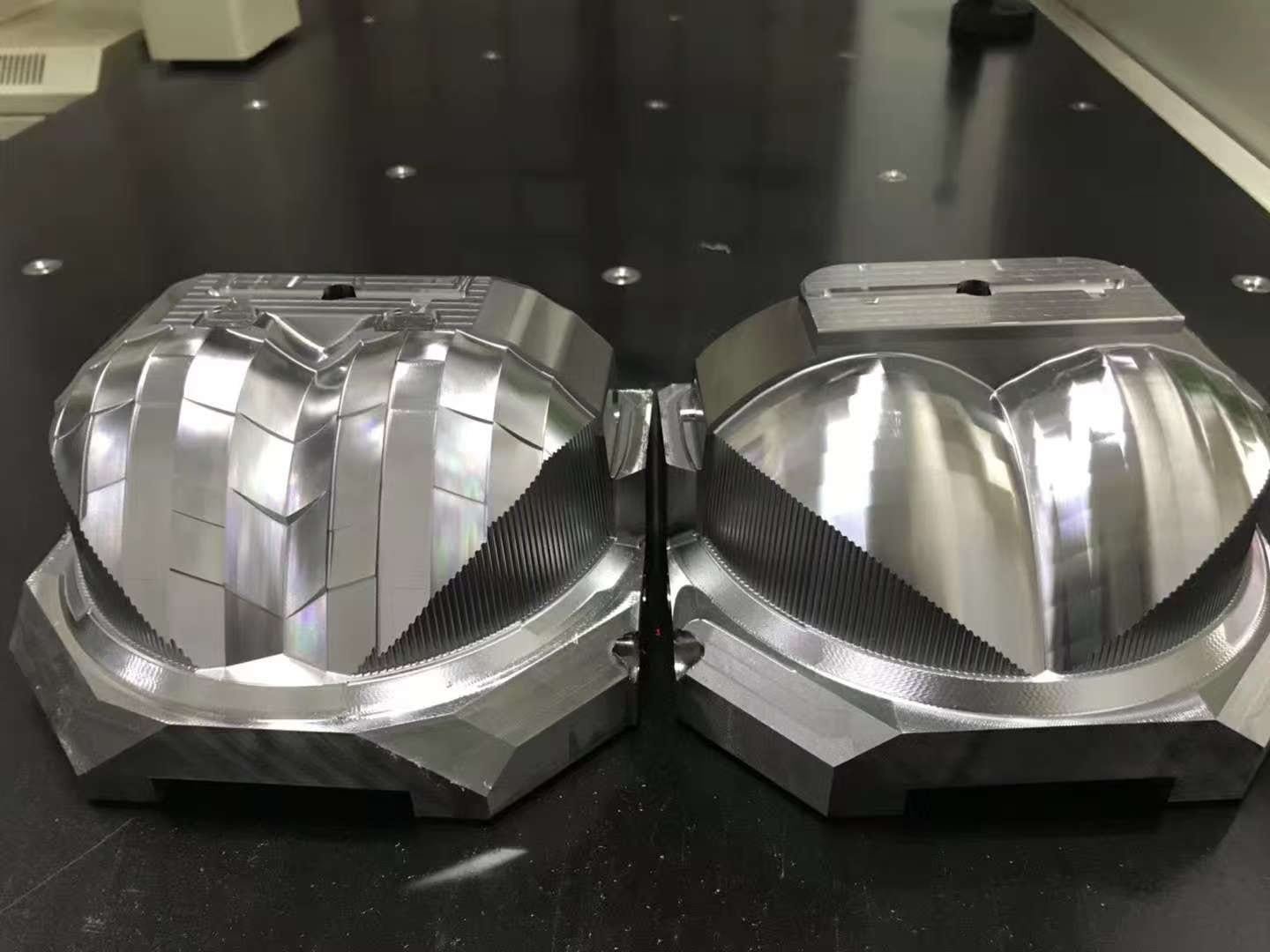 Lighting Mold Components
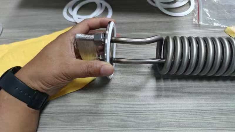 Helical Cooling Tube Assembly
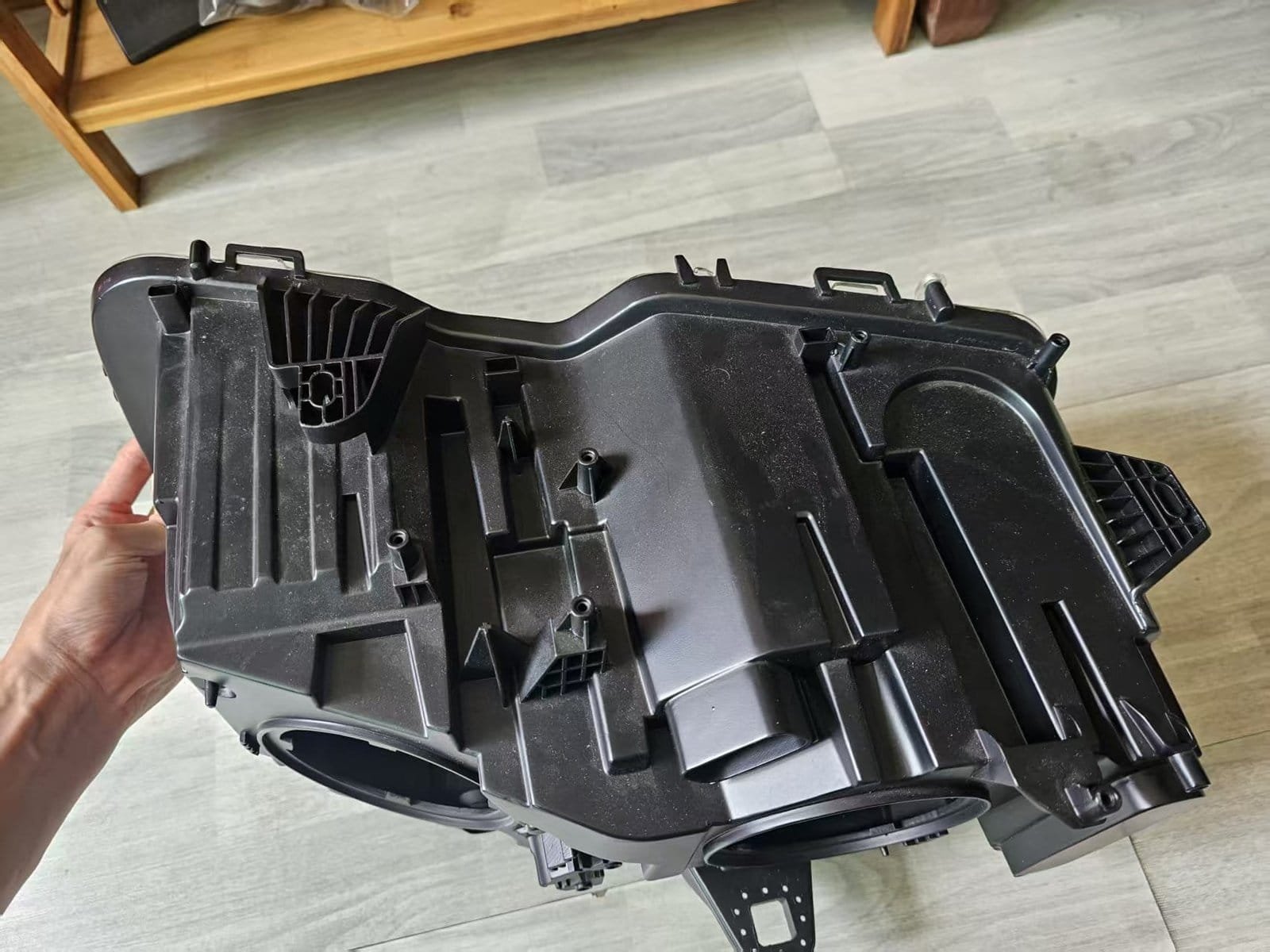 Headlamp Assembly Prototype