A 3D model describes nominal geometry. A manufacturer still needs to know which features control function, which surfaces are cosmetic, what may change and how the part will be accepted. Before requesting a quote, pair the CAD with a concise manufacturing-intent record.
Product and manufacturing information extends beyond nominal geometry to tolerances, surface requirements and other acceptance intent. The practical RFQ lesson is that a STEP file alone rarely communicates every purchasing and acceptance decision.
Use this checklist to mark intent without prescribing an unverified manufacturing process too early.
Priority system
Apply three priorities to every marked requirement:
| Priority | Meaning | RFQ treatment |
|---|---|---|
| P0 — Decision-critical | Failure makes the prototype unable to answer its main question | Highlight on drawing/PMI and discuss before quotation |
| P1 — Functional or assembly-critical | Affects fit, interface, movement or selected function | Identify datum/interface and acceptance evidence |
| P2 — Cosmetic or secondary | Influences appearance or preference but does not block the main decision | Mark zone, reference and acceptable variation |
Do not mark everything P0. If every dimension is critical, the supplier cannot see where engineering attention matters most.
1. Files and revision
- [ ] Native or neutral 3D CAD suitable for the requested review;
- [ ] marked 2D drawing or PMI for manufacturing intent;
- [ ] revision ID and date on every controlled file;
- [ ] units explicitly stated;
- [ ] assembly CAD and mating-part data where interfaces matter;
- [ ] purchased-component specifications;
- [ ] obsolete files removed from the RFQ package.
State which file governs if 3D and 2D information conflict.
2. Prototype decision and quantity
- [ ] appearance, fit, assembly, function or testing purpose;
- [ ] decision the prototype must support;
- [ ] quantity for this revision;
- [ ] likely next-stage quantity, clearly separated from the current order;
- [ ] target evidence and review date;
- [ ] excluded functions or tests.
Quantity and production rate can affect process planning, but do not ask a supplier to assume future volume.
3. Critical surfaces and geometry
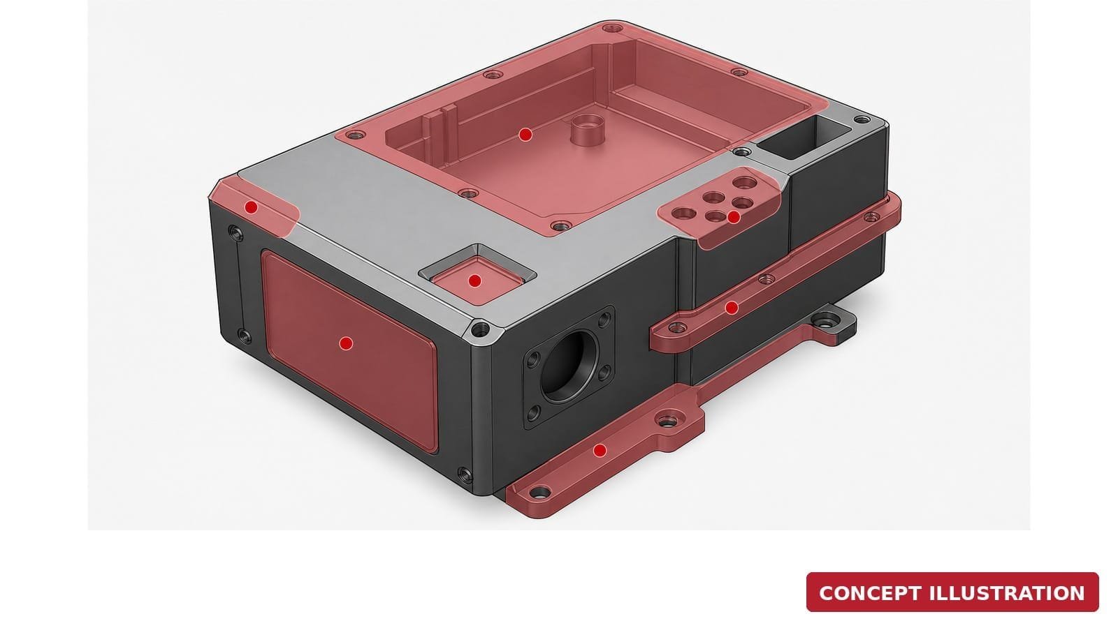
Mark directly on a drawing, screenshot or PMI view:
- datum or reference scheme;
- mating and sealing surfaces;
- form-critical freeform surfaces;
- holes, threads, slots and locating features;
- thin walls, deep pockets or inaccessible regions;
- sharp internal corners that may be functional or merely nominal CAD;
- fine repeated features and texture zones;
- no-touch or no-mark areas;
- areas where witness marks may or may not be acceptable.
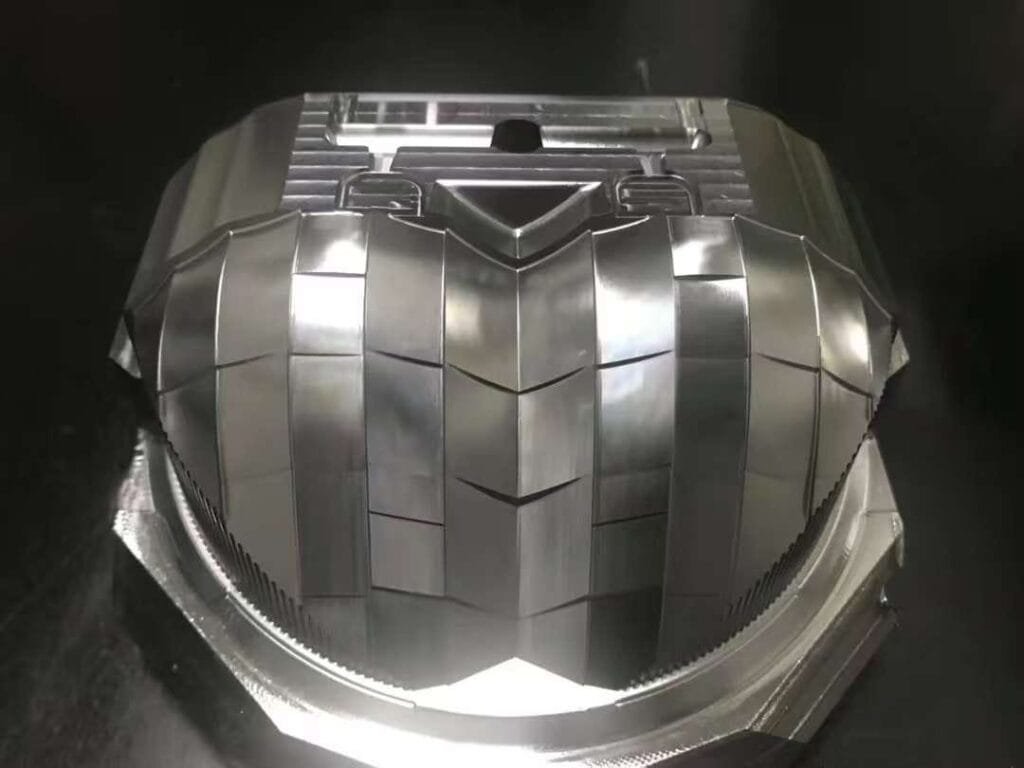
For freeform components, separate nominal form, waviness/texture and cosmetic appearance. A reflective photo does not quantify surface form or finish.
4. Interfaces and assembly
- [ ] mating-part revisions included;
- [ ] fit type or intended movement described;
- [ ] gap, flushness or clearance requirement marked;
- [ ] connector, fastener and insert specifications included;
- [ ] tool-access and assembly direction considered;
- [ ] cable, hose or component envelope supplied;
- [ ] assembly sequence or exploded view included;
- [ ] adhesive, seal or joining requirement identified only when known.
An isolated part can be manufacturable and still fail in assembly because the interface intent was missing.
5. Tolerances
- [ ] general tolerance identified where appropriate;
- [ ] critical dimensions separated from non-critical dimensions;
- [ ] datum references are consistent with function and inspection;
- [ ] unilateral/bilateral limits are clear;
- [ ] fit requirements link to mating components;
- [ ] geometric tolerances used where they communicate function better than coordinate dimensions;
- [ ] inspection method or evidence specified for P0 features;
- [ ] no copied tolerance is tighter than the decision requires.
ASME Y14.5 is a major reference for dimensioning and tolerancing practice, but merely placing GD&T symbols on a drawing does not make the datum scheme functional. The drawing must still represent design intent.
6. Material intent
Specify:
- required material or acceptable property range;
- whether an exact grade is mandatory for this prototype decision;
- colour, transparency, conductivity, temperature, strength or chemical needs where relevant;
- whether a substitute may be proposed;
- certification or traceability requirement, if genuinely required;
- prohibited substances or domain-specific constraints.
If the goal is appearance only, a substitute may be acceptable. If the goal depends on material behaviour, a substitution may invalidate the result. Make the distinction explicit.
7. Finish and cosmetic criteria
- [ ] finish/texture zones mapped;
- [ ] colour reference and comparison condition provided;
- [ ] gloss, transparency or reflectivity intent stated;
- [ ] masked/no-finish areas identified;
- [ ] edge-break and burr expectations stated;
- [ ] acceptable witness marks defined by zone;
- [ ] reference sample identified where one exists;
- [ ] cosmetic approval evidence defined.
Avoid subjective instructions such as “premium finish” without a reference, zone and review condition.
8. Inspection and evidence
For each P0/P1 characteristic, choose the required evidence:
- visual record;
- dimensional result;
- fit trial;
- assembly record;
- functional test;
- external compliance report, where applicable.
Do not request a full inspection report by habit. Ask for evidence that supports the decision, and identify who controls the method and acceptance rule.
9. RFQ minimum input
Company / contact:
Part or assembly name:
CAD and drawing revision:
Units:
Prototype decision:
Current quantity:
Critical surfaces and interfaces:
P0/P1 characteristics:
Material intent and substitutions allowed:
Finish/cosmetic zones:
Mating and purchased components:
Inspection/evidence required:
Excluded tests or requirements:
Requested review date:
Attach STEP plus a marked PDF or equivalent controlled PMI view. Remove commercial or customer information that is not needed for quotation.
Common RFQ failures
- Only a STEP file: nominal geometry arrives without criticality or acceptance intent.
- Everything tightly toleranced: cost and inspection grow while true functional priorities remain hidden.
- Missing mating data: the supplier cannot evaluate fit or assembly interfaces.
- Finish described by adjectives: colour, gloss and texture have no shared reference.
- Prototype and production requirements mixed: the current decision and future assumptions become unclear.
- Testing requested without acceptance: evidence is collected but cannot close the decision.
- Revision ambiguity: quote, build and review refer to different files.
Project-record connections
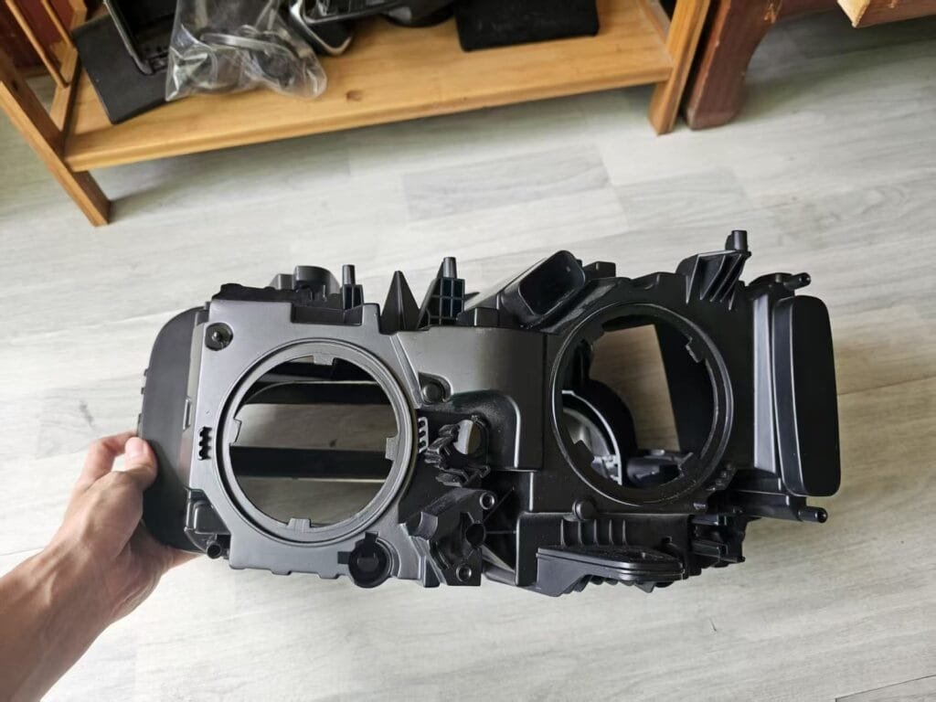
The Lighting Mold Components Project Record can show where a buyer may need to mark freeform, reflective and fine-patterned zones, but the images do not prove material, machining route, tolerance, roughness or optical performance.
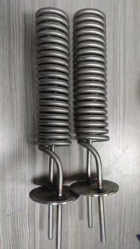
The Helical Cooling Tube Project Record can show why coil geometry, end interfaces and drawing revision should be connected in the RFQ. Its images do not prove material, joining specification, pressure, leak or flow performance.
Get Quote
Send STEP + a marked drawing + the RFQ minimum input. ProtoManu can review the request without guessing which surfaces, interfaces and evidence matter most.
CTA: Get Quote
FAQ
Is a STEP file enough for a manufacturing quote?
It may be enough for an initial geometry review, but it usually does not communicate every tolerance, cosmetic zone, interface, material condition or acceptance requirement.
Should every dimension have a tight tolerance?
No. Tolerances should follow function, assembly and the decision being tested. Separate critical characteristics from general dimensions.
What should I mark on CAD before quotation?
Mark critical surfaces, interfaces, datums, fit requirements, P0/P1 characteristics, material intent, finish zones, assembly constraints and required evidence.
Can the manufacturer choose the process?
You may invite a process recommendation when the prototype decision permits it. If a process or material is mandatory for the evidence, state why and control it in the RFQ.
Sources
- DFMA, Design for Manufacturing: https://www.dfma.com/design-for-manufacturing.asp
- ASME, Y14.5 Dimensioning and Tolerancing: https://www.asme.org/codes-standards/find-codes-standards/y14-5-dimensioning-tolerancing
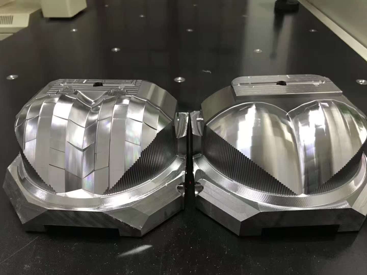 Lighting Mold Components
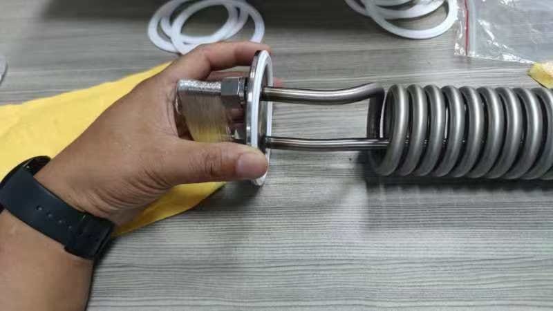 Helical Cooling Tube Assembly